Plunger Assisting Multiphase Pump (PAMP)

The PAMP, can stimulate your well’s plunger operations by removing the fluids above the plunger and reinjecting the gas through the annulus to increase run efficiency and decrease the down-time for pressure accumulation.

With the dramatically increasing worldwide demand for natural gas and gas liquids the producers can now benefit from new technology which can better support production from liquid rich and low-pressure reservoirs.

Liquid loading is primarily mitigated with plungers where the well pressure controls the up-travel of the plunger and has to operate against low or zero backpressure to work. Normally to over-come the liquid column flaring or venting is necessary, and the liquids end up in a blow down tank and have to be transported away separately from site. Alternative to plunger assisted compres-sors with blow case systems, the Leistritz PAMP can handle the liquids effectively without down-time or maintenance issues..

Unlike a compressor the PAMP uses a twin-screw multiphase pump which brings significant ad-vantages:

Gas Well Deliquification Technology – Where Plunger Lift Meets Multiphase Pumping
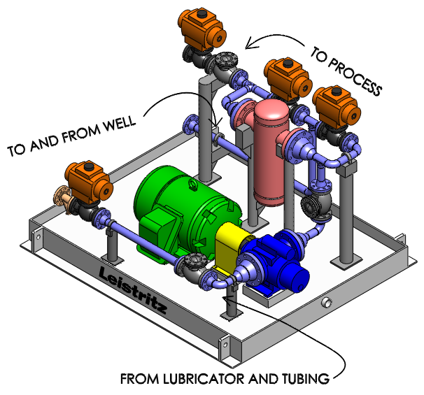
Plunger Assisting Multiphase Pump

Scope of Supply

  • Handles from 100% gas to 100% liquids without interruption
  • Pressurizes liquids and gas back through the annulus for efficiently lifting the plunger
  • Can boost gas and liquids to line pressure in one step
  • Boosting pressure unrelated to suction pressure
  • No pressure ratio limitation like a compressor
  • Can be natural gas engine or electric motor driven
  • Portable for distributed well service

Background on PAMP

The Leistritz Blow down Unit (BDU) with a twin-screw multiphase pump has shown to be very effective deliquifying liquid loaded gas wells in the Piceance Creek play for several years. The PAMP builds on experiences gained by the BDU, which works without a plunger and instead low-ers the tubing pressure to reach critical velocity in order to escape liquids. As with the PAMP the BDU boosts the combined gas/liquid stream in an uninterrupted fashion.

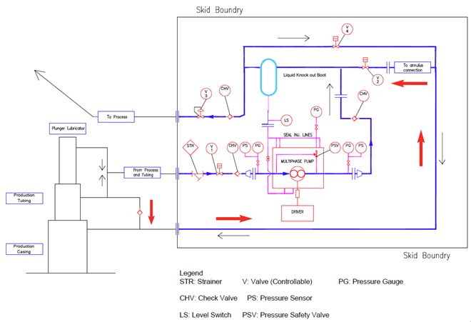
The P&ID below shows the flow path and operating sequence of the PAMP:

Plunger Assisting Multiphase Pump
  1. Normally flowing through V2 and V3.
  2. Well gets liquid loaded. Flow drops and V3 closes.
  3. Plunger drops and MPP gets ready to start.
  4. After preset time (=plunger drop),V1 & V4 open, V2 closes and the MPP starts
  5. MPP draws gas and liquids from tubing and lubricator and pumps it to the annulus.
  6. Plunger reaches the lubricator pushed and pulled by the MPP.
  7. V3 opens and V4 closes and MPP flows down stream.
  8. When steady flow is reached MPP stops, V1 closes and V2 opens. Well now flows freely.